

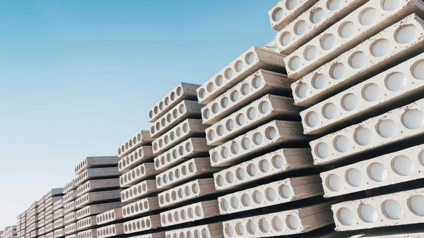
Precast concrete reduces construction time mainly by moving curing and quality-control work off-site and ahead of the installation date — so on-site work shifts from a construction sequence to a shorter installation sequence, most clearly for compound walls, drainage and retaining structures. “Precast saves time” is a common claim — worth unpacking into where the time actually comes from, and where it doesn’t. Where the time saving is real Curing happens off the critical path. Concrete needs time to cure regardless of method; precasting lets that curing period run in parallel with other site work, rather than blocking the boundary or drainage trade on site. Installation replaces multi-trade sequencing. A precast compound wall install (post erection, panel placement, jointing) is a shorter, more predictable sequence than excavation, masonry, plastering and curing carried out trade-by-trade on site. Weather has less impact. Once elements are cast and cured, on-site placement is far less sensitive to weather than wet trades like masonry and plastering. Where precast doesn’t automatically save time Custom or first-of-type elements still need drawing review, mould preparation and casting lead time before delivery — plan this into the programme rather than assuming stock availability. Site access and lifting for precast elements needs planning; a site without crane or lifting access may see less benefit than one that has it. Foundation work for posts, retaining wall bases or drain bedding still has to happen on site, on its own timeline. How to plan a project around precast lead times Share your target delivery date early — production is scheduled against mould availability and your stated timeline (see the Manufacturing Process page). For custom precast work, share drawings as early as possible so technical review doesn’t become the bottleneck.
Earth Retaining Walls for Industrial and Infrastructure Projects
An earth retaining wall holds back soil at a change in ground level. For industrial and infrastructure projects, precast L-shaped retaining walls are engineered against project-specific soil, load and drainage conditions — not a single standard dimension. Industrial plots and infrastructure corridors often include a change in ground level — a platform cut into a slope, an embankment beside a road, or a level difference between adjacent plots. An earth retaining wall is the structure that makes that level change safe to build and work around. What the wall actually has to resist A retaining wall’s design has to account for several things at once: the weight of the retained soil, the soil’s angle of internal friction, any surcharge or overburden load on top of the retained ground, and the ground’s own bearing strength beneath the wall’s foundation. Two standard checks that typically govern the design are a sliding safety factor and an eccentricity limit for overturning. Why drainage detailing matters Water pressure building up behind a retaining wall is one of the most common causes of retaining-wall distress. That’s why drainage holes through the wall stem, paired with a soil-particle stop filter, are part of standard detailing on 3Bro Precast’s earth retaining wall — relieving hydrostatic pressure while limiting fines migrating into the drainage path. Why precast, for this application Precasting an L-shaped retaining wall shifts the curing period off the project’s critical path compared to shuttering and pouring the wall in place — useful on industrial and infrastructure programmes where the retaining structure often has to be in place before other site work can proceed. The one thing every project should hear Final retaining wall configuration depends on soil conditions, surcharge loads, drainage, foundation and engineering design — dimensions referenced on product pages are starting points, not a specification that applies uniformly to every site. See the Earth Retaining Wall product page for full technical detail.
T-6 vs T-25 U Shape Drain: Understanding Project Requirements
T-6 is the standard-duty U shape drain, suited to pedestrian and light-vehicle areas; T-25 is the heavy-duty option, engineered for carriageways, industrial yards and infrastructure sites where heavier axle loads cross the channel. Choosing between the T-6 and T-25 U shape drain comes down to one question: what’s going to cross the channel? T-6: standard-duty drainage T-6 U drains are designed for footpaths, residential layout drainage, light-vehicle parking and access areas, and general site perimeter drainage. See the T-6 product page for reference dimensions across the standard nominal size range. T-25: heavy-duty drainage T-25 U drains are designed for locations where vehicles with heavier axle loads pass over or alongside the channel — carriageways, industrial yards, and infrastructure or utility corridors. See the T-25 product page for reference dimensions. How to decide Situation Recommended class Footpath or pedestrian zone T-6 Residential internal road, light-vehicle parking T-6 Carriageway-adjacent drainage T-25 Industrial yard with truck circulation T-25 Uncertain / mixed traffic Confirm with the technical team A note on getting it right Specifying too light a load class risks premature damage to the lid or channel; over-specifying adds unnecessary cost. Share your project’s traffic and axle-load expectations with the 3Bro Precast technical team before finalising a size and class.
U Shape Drains for Stormwater Management: Applications and Benefits
Precast U shape drains manage stormwater by carrying surface water in a factory-cast, U-section channel laid along a designed route, closed with a removable precast lid — sized and load-rated to suit the site above it. Stormwater management on almost any Bangalore site comes down to the same question: how do you get surface water off the site, predictably, without breaking up the ground every time the channel needs clearing? Precast U shape drains are one answer. Where U drains fit into a stormwater strategy U drains typically sit at the collection stage of a site’s drainage design — running alongside roads, footpaths, boundary walls or paved yards to intercept and carry surface water to an outfall or connection point. Because they’re precast, the channel profile stays consistent along the whole run, which supports predictable flow. What to plan for when specifying Channel size: matched to expected catchment area and flow, referenced against standard nominal sizes (see the U Shape Drain page). Load class: T-6 for pedestrian and light-vehicle areas, T-25 for carriageway and heavier-duty applications — see T-6 and T-25. Bedding and fall: channels are laid on a prepared PCC bed to a designed level and fall so water actually moves along the run. Maintenance access: precast lids keep the channel serviceable without breaking out concrete. Benefits over cast-in-situ drainage Casting the channel off-site means the profile is consistent and the trench time on site is largely limited to excavation, bedding and jointing — rather than shuttering and pouring a channel in place.
What Is a 75mm Precast Compound Wall?
A 75mm precast compound wall is a single-piece cast concrete boundary wall panel, nominally 75mm thick and reinforced with TMT bar, installed between precast posts as part of the wider precast compound wall system. The “75mm” in a 75mm precast compound wall refers to the panel’s nominal thickness — a slim, single-pour panel designed as a lighter option within the broader precast compound wall product family. How it’s cast Each panel is cast as one piece, with reinforcement (TMT bar, and in some configurations weld mesh) running through the panel body, in M30-grade concrete. Because the panel is cast in a single pour, there’s no layering or on-site build-up — the panel arrives at site ready to install. Where it’s used Industrial and factory perimeter walls Warehousing and logistics site boundaries Residential and layout boundaries Sites where a lighter panel simplifies handling and logistics What to check before specifying Panel thickness is only one input into overall wall performance — post spacing, foundation design and wind/soil loading also matter. See the full product page for reference dimensions and specification notes, and confirm current production specification with the 3Bro Precast technical team before ordering.
Precast Compound Wall vs Traditional Brick Wall: What Should Projects Choose?
Precast compound walls install faster and offer more consistent quality than traditional brick walls, because panels are cast and cured off-site; brick walls remain a familiar, highly customisable option built entirely on site. The right choice depends on programme, budget and site conditions. Choosing between a precast compound wall and a traditional brick-and-mortar wall is one of the first decisions on many Bangalore projects — and it’s worth making deliberately rather than by habit. When precast makes the most sense Precast tends to be the stronger fit when programme matters — long boundary runs on a tight schedule, projects where masonry labour is hard to secure, or sites where a consistent finish across many linear metres is important (residential layouts, industrial perimeters, warehousing). When brick still has a role Site-built brick walls remain well suited to short runs, irregular boundary geometry, or projects that need bespoke architectural detailing that isn’t yet part of a standard precast panel range. Practical considerations Confirm required wall height and post spacing against your boundary layout before comparing costs. Ask for a written specification either way — panel/post dimensions for precast, or brick/plaster spec for masonry. Factor in weather and labour availability for your specific build window, not just headline cost per metre.